Seeed Studio
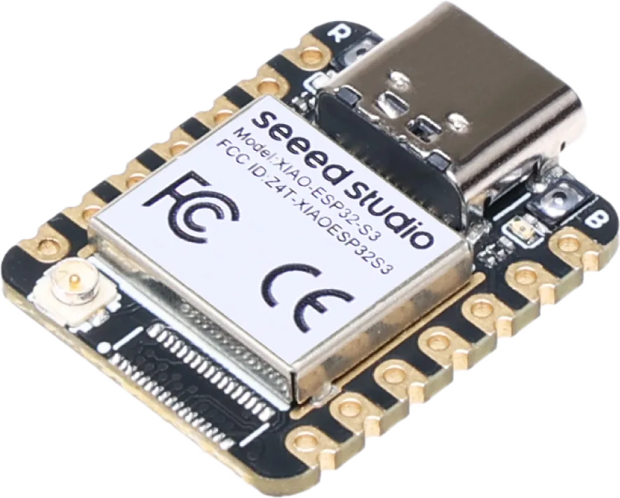
Seeed XIAO ESP32-S3 Fit Wi-Fi and Bluetooth control into a small custom board.
Build & code Bluetooth LE
Bring along USB cable, antenna and the peripherals required by your firmware.
Keep in mind Base board lacks Sense camera/microphone and a dedicated battery-voltage ADC. Source checked · Sep 16, 2026 Image credit Maker image · base XIAO ESP32S3 · Seeed Studio CC BY-SA 4.0 · Original image file unchanged; resized for display. A copy with the background removed is shown in the catalogue. Original image
Overview Blueprint 4 Specifications 31 Resources 11
(02) Blueprint
What’s published Seeed publishes the schematic PDF, a dimensioning drawing, and the chip datasheet for the XIAO ESP32S3; the related GitHub repo has only a footprint/pinout library, not the module's own PCB source.
1 git clone https://github.com/Seeed-Studio/OSHW-XIAO-Series.git
Research notes A 'Plus' variant schematic and a separate ExpBoard breakout also exist on files.seeedstudio.com but are different accessory boards, not listed here since this device slug is the base ESP32S3 module.
Every link checked 2026-09-27.
Hand this device to your agent. Everything on this page, as clean Markdown and JSON: specs, shops, prices, design files, parts.
Made the Seeed XIAO ESP32-S3? Put the badge on your README; it links here, with every shop that sells it.
Copy Markdown
Base board 5 Processor ESP32-S3R8; dual-core 32-bit Xtensa LX7 up to 240 MHz Memory 8 MB PSRAM and 8 MB flash; Plus has 16 MB flash Wireless 2.4 GHz Wi-Fi and Bluetooth LE Antenna External U.FL antenna; attach the supplied antenna for wireless use Interfaces & power 17 USB USB-C power/programming; nominal 5 V Battery 3.7 V rechargeable battery support and charge management Buses 11 digital/PWM pins; 9 ADC channels; one UART, I²C and SPI bus I²C pins D4/GPIO5 SDA; D5/GPIO6 SCL UART pins D6/GPIO43 TX; D7/GPIO44 RX SPI pins D8/GPIO7 SCK, D9/GPIO8 MISO, D10/GPIO9 MOSI Controls Boot, reset and active-low user LED on GPIO21 Low-power figures Base board: 27 mA modem sleep, 2 mA light sleep, 14 µA deep sleep at 3.8 V, typical maker values Analog header pins D0–D3 map to GPIO1–GPIO4. 3V3 output Wiki rates the regulated 3.3 V output at 700 mA. External 5 V Maker requires a diode when feeding the 5 V pin externally. Battery-only limit The 5 V pin has no output when powered only by the battery. Battery monitoring Base board has no dedicated battery-voltage ADC connection. Charging figures Base-board table: 50 mA fast charge; 3.8 mA trickle, typical. Active current Typical base-board figures: Wi-Fi 100 mA; BLE 85 mA. V1.4 power components Published V1.4 schematic: SGM40567-4.2 charger; SGM6029 regulator. Variants & setup 9 Base package Pin headers are not installed by default Sense expansion Camera, digital microphone and microSD slot are on the Sense expansion board Camera revisions Later Sense batches use OV3660 instead of discontinued OV2640; optional OV5640 also supported Plus difference Its board connector supports Wio-SX1262; it is not compatible with the plug-in camera board Programming Arduino: select XIAO ESP32-S3. MicroPython is also documented. Pin caveat GPIO41/42 do not support ADC despite analog labels in parts of the wiki USB recovery Hold BOOT while connecting a data-capable USB cable, or hold BOOT and press reset. Reset-sensitive pins GPIO0/46 choose boot mode; GPIO45 affects flash voltage; GPIO3 selects JTAG source. Factory demo Base firmware lights the user LED when a touch-capable pin is touched. No matching specification. Try a chip name, connector or feature.
What still needs checking Do not apply Sense camera/microphone/SD or Plus expansion specifications to the base board. Battery charging and runtime vary with the selected variant.
Downloads & docs
From the original makers Build with Seeed XIAO ESP32-S3 Source & revision notes Maker listing checked Sep 16, 2026. Detailed documentation reviewed Sep 16, 2026. Not hands-on tested.
Price is a dated listing; confirm with the maker.
This entry covers XIAO ESP32-S3, not Sense or Plus. Those variants have different peripherals and memory configurations.
Battery pads and charging support do not mean a battery is included. Check pin voltage, battery polarity and antenna connection in the linked guide.
The base board cannot read battery voltage directly, and its 5 V pin is unpowered on battery alone. Power figures in the guide are typical values for the named variant, not measured runtime for a complete build.
Price US$7.49 read from the maker's store on 2026-09-18.
The linked base schematic is V1.4; older dimension drawings have their own revision labels. Confirm your PCB revision before using power-component or expansion details.
Build or list hardware with us