Dangerous Prototypes
Bus Pirate 5 Rev. 10 Talk to chips over serial buses before writing a full application.
Build & code
Bring along USB host with a terminal, probe leads and a compatible target circuit.
Keep in mind Match the firmware to the Bus Pirate model and PCB revision. Source checked · Sep 16, 2026 Image credit Project image · revision 10 · Dangerous Prototypes
Overview Blueprint 5 Specifications 24 Resources 10
(02) Blueprint
Build it yourself Full KiCad schematic/PCB source, an interactive BOM, and an STL enclosure for Bus Pirate 5 Rev10 are published in Dangerous Prototypes' official hardware repo and docs site.
Schematic 6 sheets Board 3 boards 3D 5 models Bus Pirate 5 Rev10a KiCad project (schematic + PCB)
Read straight from the maker’s repository. Open on GitHub
Bus Pirate 5 Rev10a KiCad project (schematic + PCB)
GitHub
2 git clone https://github.com/DangerousPrototypes/BusPirate5-hardware.git
Research notes Verified BusPirate5-hardware repo tree via gh api (recursive): bus_pirate_pcb/5-REV10A/REV10a.kicad_pro/.kicad_pcb/.kicad_sch plus sub-sheets exist alongside enclosure/BusPirate5REV10-v0.stl; both GitHub blob links and the docs.buspirate.com schematic PDF returned HTTP 200. Repo is MIT-licensed and also contains many other BP5 adapter boards (fully open). RP2040 datasheet URL 301-redirects to pip.raspberrypi.com but resolves successfully. The interactive BOM HTML and the 5-REV10A tree URL were also checked (200). The display driver IC is not named on the introduction page (only '320 x 240 pixel IPS'); check the KiCad schematic for it.
Every link checked 2026-09-27.
Hand this device to your agent. Everything on this page, as clean Markdown and JSON: specs, shops, prices, design files, parts.
Made the Bus Pirate 5 Rev. 10? Put the badge on your README; it links here, with every shop that sells it.
Copy Markdown
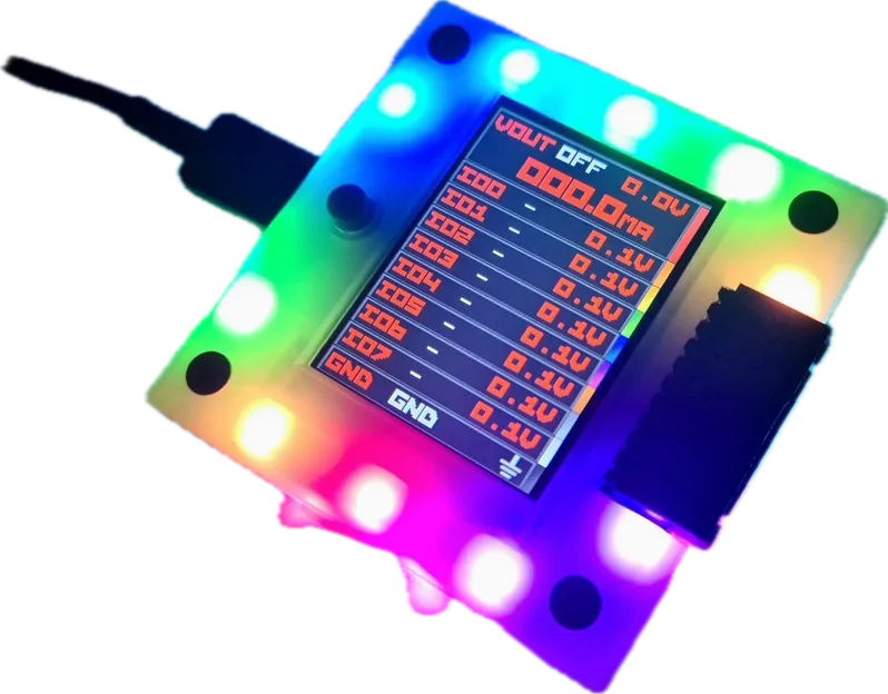
Bus Pirate 5 revision 10 8 Processor and flash RP2040; 128 Mbit (16 MB) firmware flash. Buffered I/O Eight tri-state pins; stated operating range 1.65–5 V. Pin tools Voltage measurement per pin and switchable 10 kΩ pull-ups. Connectors 10-pin 2.54 mm main header; 9-pin 1 mm auxiliary header. Storage 1 Gbit (128 MB) NAND exposed as USB storage for settings/files. Status display 320 × 240 IPS; pin labels, voltages and supply current. Controls One button and 18 RGB LEDs. USB USB-C; data speed is limited by RP2040 hardware. Target wiring and power 7 Target supply 1–5 V output; rated maximum 300 mA. Protection setting 0–500 mA current-limit range; extra headroom is for transients, not a 500 mA output rating. Supply behavior Disabled in HiZ mode; current-limit trips shut the supply off. Main-header map Pin 1: VOUT/VREF; pins 2–9: IO0–IO7; pin 10: target ground. External reference VOUT/VREF can accept a target reference to power the I/O buffers. Accessory requirement Probe and auxiliary cable kits are separate listed products; verify the purchased bundle. Firmware-controlled pins Protocol functions vary by mode; use the displayed pin labels and official pin map. Setup and model boundaries 9 Terminal Use a serial terminal; quickstart specifies 115200 baud, 8-N-1 and VT100. Two serial ports One is the terminal and one is binary access; numbering is not guaranteed. Platforms Official quickstart provides Windows, Linux and macOS terminal paths. Protocol reference SPI, I²C, UART and other modes have separate commands and limits. Revision-specific image Production rev10 uses bus_pirate5_rev10.uf2; rev8 engineering samples use their own image. Bootloader RP2040 hardware bootloader exposes RPI-RP2 for UF2 updates; recovery instructions are linked. Newer boards Bus Pirate 6 uses a different RP2350 image; match board/revision before flashing. Design files Rev10 hardware documentation links schematics, component placement and an interactive BOM. Firmware channel Official downloads are automated builds from main; review the build and revision before updating. No matching specification. Try a chip name, connector or feature.
What still needs checking The reviewed pages do not establish an absolute maximum input voltage for every external pin; 1.65–5 V is the stated buffered operating range. Probe kit contents depend on the order; no host-terminal or accessory bundle is implied.
Downloads & docs
From the original makers Build with Bus Pirate 5 Rev. 10 Source & revision notes Maker listing checked Sep 15, 2026. Detailed documentation reviewed Sep 16, 2026. Not hands-on tested.
Price is a dated listing; confirm with the maker.
Rev. 10 has eight buffered I/O pins and a 1–5 V target supply rated for 300 mA. The 0–500 mA configurable protection limit provides transient headroom; it is not a continuous output rating.
The onboard screen shows status; interaction uses the host terminal. The display and power supply do not make it a stand-alone oscilloscope or universal programmer.
Detailed documentation reviewed 2026-09-16; this does not refresh price or stock checks or establish hands-on testing.
Price is Lab401's euro listing on 2026-09-18, not the maker's own price; both variants were in stock.
Rated supply output is 300 mA. The broader 0–500 mA current-limit setting must not be advertised as continuous output capacity.
This profile targets Bus Pirate 5 rev10, not the older rev8 preview, 5XL or Bus Pirate 6.
Build or list hardware with us Bus Pirate 5 Rev. 10 Dangerous Prototypes
Buy €59+