Inside Flipper Zero
Take it apart.
Four boards, each with a distinct job. Explore their components and follow the maker’s complete teardown.
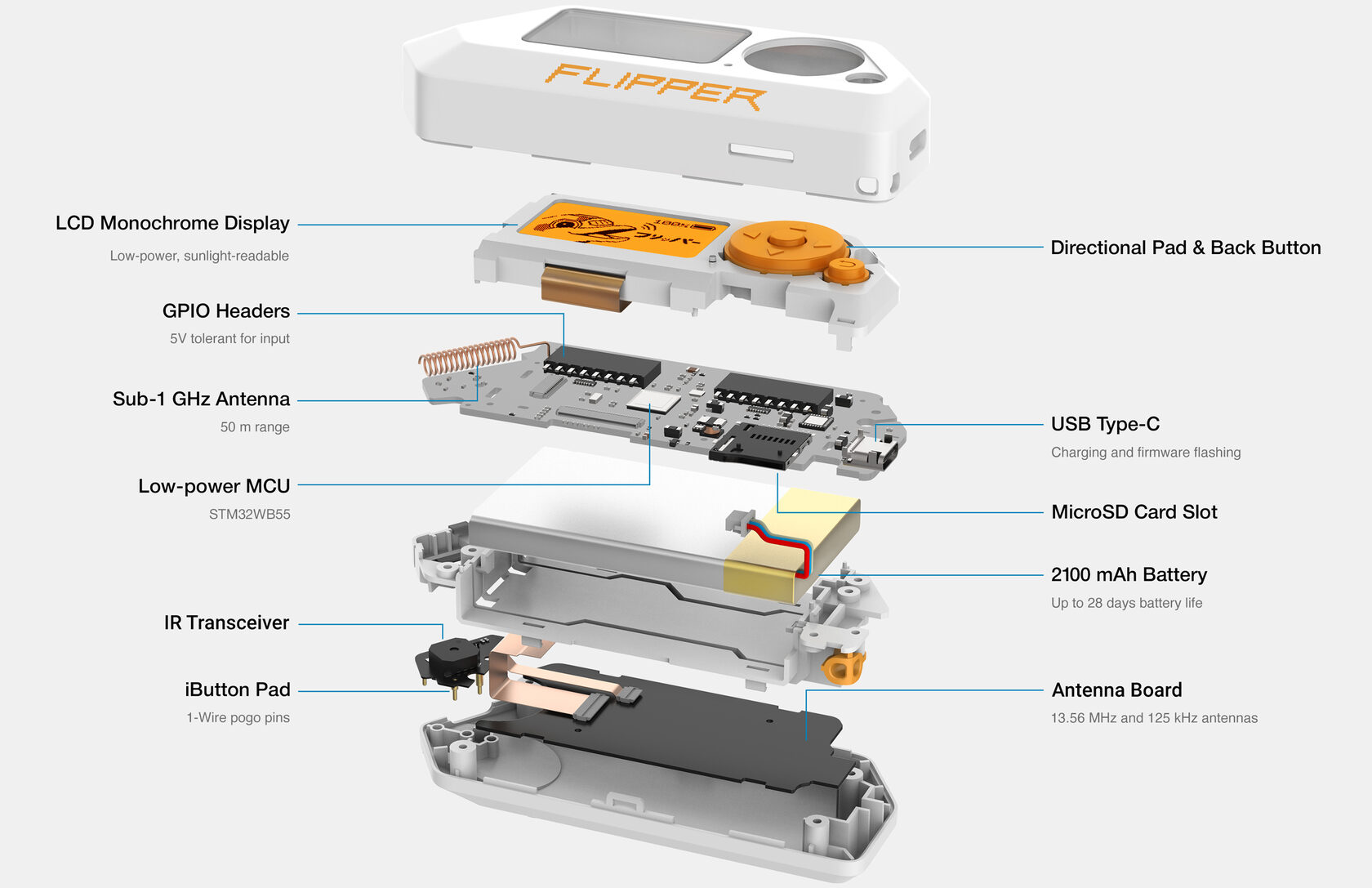
4 boards · 36 teardown steps
From the shell to the circuits.
See how the boards fit together, then inspect each one.
- Main PCBThe processor, display, controls and sub-GHz radio share the main board.
- iButton PCBContact keys, infrared and sound live on this smaller board.
- NFC / RFID PCBThe contactless electronics connect to a separate antenna board.
- Antenna PCBThe dual-band antenna sits against the bottom shell, beneath the NFC/RFID board.

12.1 · F7B9C6
Main PCB
The processor, display, controls and sub-GHz radio share the main board.
- STM32WB55
- Application processor and Bluetooth
- CC1101
- Sub-GHz transceiver
- LCD & buttons
- Display and physical controls
- USB-C & GPIO
- Power, data and expansion

12 · F7B9C6 drawing; revision 13 changes pogo-pin mounting
iButton PCB
Contact keys, infrared and sound live on this smaller board.
- iButton contacts
- 1-Wire interface
- Infrared
- Transmitter and receiver
- Piezo buzzer
- Sound output

12 · F7B9C6
NFC / RFID PCB
The contactless electronics connect to a separate antenna board.
- NFC
- 13.56 MHz interface
- RFID
- 125 kHz interface
- Power & vibration
- Power circuitry and motor connection

12 · F7B9C6 (visible on the board illustration)
Antenna PCB
The dual-band antenna sits against the bottom shell, beneath the NFC/RFID board.
- 13.56 MHz antenna
- NFC coupling
- 125 kHz antenna
- Low-frequency RFID coupling